
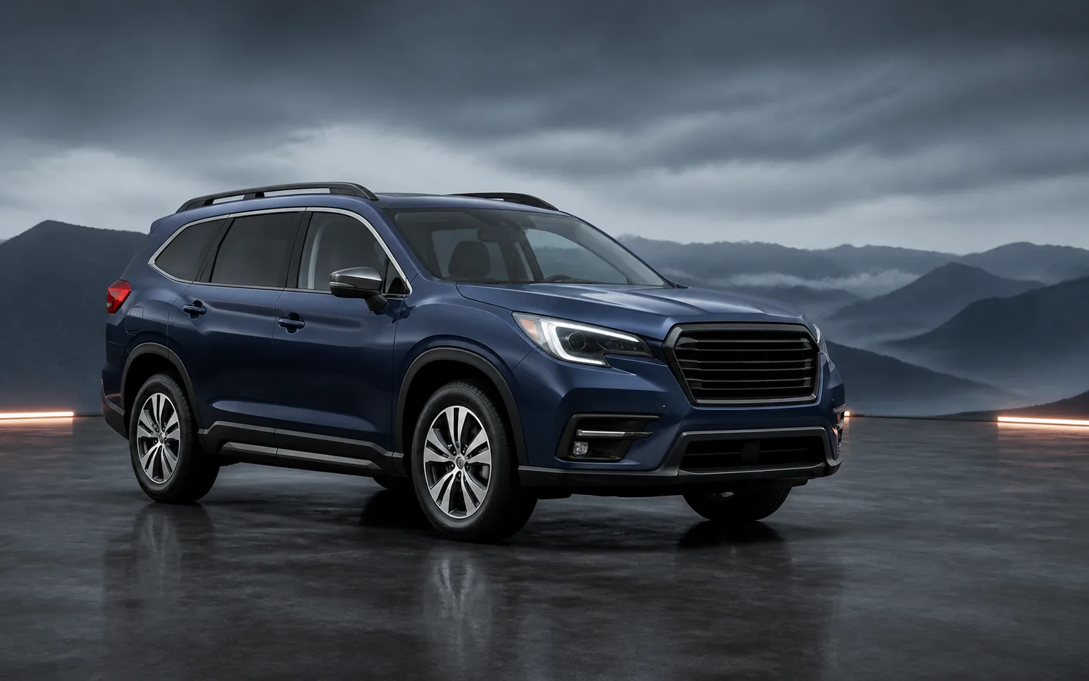
In the Subaru Ascent, the Surround View Monitor can be deactivated in several intuitive ways, depending on driving conditions and driver preference.
Manual cancellation
You can manually exit the Surround View Monitor display in the Subaru Ascent using any of the following actions.
- Press the view monitor switch repeatedly until the standard display screen appears (when the select lever is not in the "R" position).
- Shift the select lever out of the "R" position to immediately exit the rear camera view.
- Touch
 (car settings icon).
 - Touch
 (HOME).
 - Touch
 (driver profiles icon).
Automatic cancellation
The Subaru Ascent will automatically turn off the Surround View Monitor when certain conditions are met, ensuring safe and distraction-free driving.
- If the select lever is not in the "R" position:
- The system will deactivate approximately 3 minutes after activation via the view monitor switch.
- If the select lever is not in the "R" or "P" position:
- The vehicle speed exceeds 13 mph (20 km/h).
- The brake pedal is pressed and the parking brake is engaged.
- If the select lever is in "D" or "R":
- Shifting the gear to "P" will cancel the display.
How to view the camera images
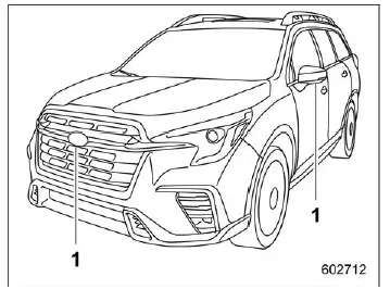
Cameras
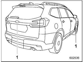
Cameras
The Subaru Ascent camera system overlays guiding lines on the display, helping you estimate distance, direction of movement, and proximity to surrounding objects or vehicles.
CAUTION
- When operating the Subaru Ascent, do not rely solely on the guiding lines.
Always visually confirm surroundings using mirrors and direct observation.
- Guidelines may not accurately represent actual distances if the vehicle is tilted due to uneven cargo distribution or passenger weight.
NOTE
- In top and rear view modes of the Subaru Ascent, predicted steering trajectory lines can be enabled or disabled through the "Steering Angle Lines" setting in the center display.
- Under certain conditions, the camera image may be difficult to interpret.
This is not a malfunction and may occur when:
- The environment is dark, such as nighttime driving.
- Extreme high or low ambient temperatures are present.
- The camera lens is wet due to rain or condensation.
- Dirt, mud, or debris is present on or near the camera.
- Strong light sources, such as sunlight or headlights, directly strike the camera lens.
- Artificial lighting (fluorescent, sodium-vapor, or mercury lamps) may cause visible flickering effects on the screen.
- When the display is cold, image trails or reduced brightness may occur, making visibility temporarily difficult.
- High humidity or nighttime conditions may cause image noise or altered colors. The Subaru Ascent system may adjust image processing to reduce noise, which can affect color accuracy.
- Differences in sharpness between the center and edges of the display are normal characteristics of the camera system.
3D view
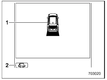
- Vehicle icon
- Vehicle angle icon
The Subaru Ascent 3D view provides a simulated perspective around the vehicle, allowing better spatial awareness when maneuvering in tight areas.
Top view
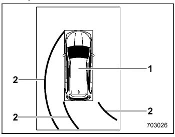
- Vehicle icon
- Predicted course line*
*: Available when the select lever is in the "R" position.
The top-down view in the Subaru Ascent displays a bird’s-eye perspective, making it especially useful for parking and navigating confined spaces.
Front view
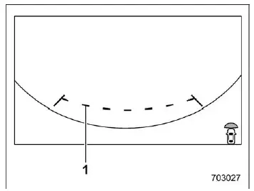
- Guiding lines
The front view in the Subaru Ascent displays guidelines indicating the vehicle width and front edge to assist with positioning.
Side view
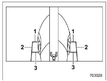
- Front-of-vehicle guiding line
- Side-of-vehicle guiding line
- Center-of-front-tire guiding line
The side view provides additional visibility of the Subaru Ascent sides, helping with precise alignment when parking or maneuvering close to obstacles.
Rear view
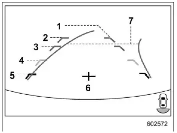
- Vehicle width line (oblique vertical line)
- Approx. 10 ft (3 m) from the bumper (green horizontal line)
- Approx. 6 ft (2 m) from the bumper (green horizontal line)
- Approx. 3 ft (1 m) from the bumper (yellow horizontal line)
- Approx. 1.5 ft (0.5 m) from the bumper (red horizontal line)
- Vehicle centerline
- Dynamic guidelines
The Subaru Ascent rear camera view includes detailed distance markers and dynamic guidelines, helping the driver judge spacing and trajectory more accurately when reversing.
The Subaru Ascent Surround View Monitor system delivers enhanced visibility and confidence, making complex maneuvers simpler and improving overall driving safety in both urban and tight parking environments.
Related manual topics
Brake fluid
Checking the fluid level
WARNING
Prevent brake fluid from coming into contact with your eyes when servicing
your Subaru Ascent, as it can cause serious irritation or injury. If exposure
occurs, rinse immediately with clean water and seek medical attention if necessary.
Wearing protecti ...
User recognition function
WARNING
Always complete registration, retrieval, or deletion of seat position and
outside mirror angle settings before starting to drive the Subaru Ascent. Attempting
to adjust or manage these personalized settings while the vehicle is in motion can
distract the driver and significantly incre ...