

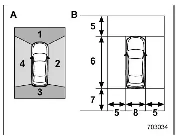
- Camera to be used
- Range of displayed image
- Front camera
- Side camera (right-hand side)
- Rear camera
- Side camera (left-hand side)
- Approx. 6 ft (2 m) from the vehicle
- Vehicle overall length
- Approx. 8 ft (2.5 m) from the vehicle
- Vehicle overall width
In the Subaru Ascent, the Surround View Monitor system combines multiple cameras to generate a comprehensive visual representation around the vehicle. Each camera contributes to a stitched image, allowing the driver to better understand the position of the Subaru Ascent relative to nearby obstacles.
The displayed area typically includes a zone extending several feet around the Subaru Ascent, but it is important to understand that this coverage is not unlimited and may vary depending on environmental and vehicle conditions.
WARNING
The visible range of the Subaru Ascent camera system is restricted. Never rely solely on the monitor display when driving. Always check your surroundings directly and proceed at low speed. Failure to do so may result in accidents or personal injury.
NOTE
- The displayed viewing range in the Subaru Ascent may change depending on vehicle load, suspension angle, and road surface conditions.
- Because the Subaru Ascent Surround View Monitor uses wide-angle lenses, the perceived distance on the screen may differ from actual real-world distances.
Using the camera
CAUTION
To maintain proper operation of the Subaru Ascent Surround View Monitor, follow these guidelines carefully.
- Avoid striking the camera units with objects or applying excessive force. Even a minor impact can alter the camera alignment and affect image accuracy in the Subaru Ascent.
- The camera units are sealed and waterproof. Do not attempt to disassemble, modify, or tamper with them under any circumstances.
- Do not scrub the camera lens aggressively or clean it with hard brushes
or abrasive materials.
Scratches on the lens can degrade image clarity and reduce the effectiveness of the Subaru Ascent camera system.
- The lens surface may be made of glass or specialized plastic. Prevent contact with chemicals such as organic solvents, wax, oil removers, or coating agents. If such substances come into contact, clean them immediately.
- Do not subject the camera lens to rapid temperature changes, such as pouring hot water on it in cold weather, as this may damage the lens or internal components.
- When washing the Subaru Ascent, avoid directing high-pressure water jets at the camera or its surrounding area. Excessive pressure may loosen the camera or allow water intrusion, leading to malfunction.
- If the camera system is exposed to impact or damage, have it inspected by a SUBARU dealer as soon as possible to ensure proper operation.
- Do not use steam cleaners on or near the camera units. High-temperature steam can damage internal components of the Subaru Ascent camera system.
- Be aware that debris such as small stones can strike and damage the camera surface during driving.
NOTE
If the camera lens becomes dirty, the Subaru Ascent system may not provide a clear image. Remove dirt, water droplets, snow, or mud by rinsing with clean water and wiping gently with a soft cloth. For heavy contamination, use a mild neutral detergent to restore proper visibility.
The Subaru Ascent Surround View Monitor is designed to enhance driver awareness, but it should always be used as a supplementary aid alongside direct observation and safe driving practices.
Related manual topics
Specifications
Specifications
Dimensions
*1: All measurements for the Subaru Ascent are taken with the vehicle in an unloaded
condition, ensuring standardized reference values.
Engine
Fuel ...
Fuel filler lid and cap
Locations of the fuel filler lid
Refueling
When refueling the Subaru Ascent, it is strongly recommended that the process
be handled by a single person to maintain safety and control. Keep other individuals
away from the fuel filler area while refueling is in progress.
Always follow all sa ...